I believe sensor projects are one of the best ways to use a Raspberry Pi. A Pi can easily be setup to collect data from sensors, and use that data to make decisions. This is fundamental to many great Raspberry Pi projects. When getting started with Raspberry Pi sensor projects, you might be wondering how to even connect a sensor to the Pi. In this guide I’m going to show you how to connect a sensor to the Raspberry Pi.
Most sensors connect to the Raspberry Pi’s GPIO. Digital sensors can connect directly to the GPIO, while analog sensors need to connect via an analog-to-digital converter. Additional components such as small resistors or capacitors may need to form part of the circuit for the sensor. Sensors connected to the GPIO can be read using the Rpi.GPIO library for Python.
I made a video demonstrating the steps of connecting a sensor to a Raspberry Pi, check it out here:
In this guide below I walk you through:
- How to identify which GPIO pin to use
- How to wire the circuit to the Rasperry Pi GPIO
- How to write code to read in from the sensor
Step 1: Identify which GPIO pins to use
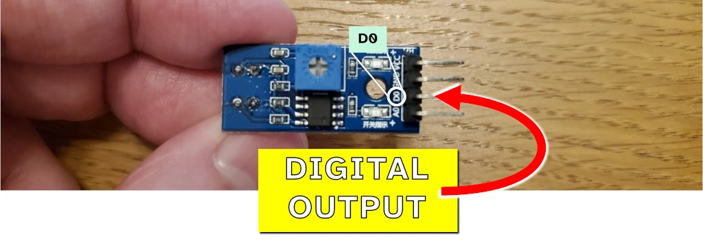
Most sensors will connect to the Raspberry Pi GPIO directly or through an analog-to-digital converter (ADC). This depends on the type of output that the sensor is capable of: A sensor’s digital output can connect directly to the GPIO, but if you want to use the analog output it will need to be connected to an ADC first.
The table and diagram below list GPIO pins you can use to connect a sensor to a Raspberry Pi, based on the output of the sensor:
| Sensor output | Pins (example) |
|---|---|
| Digital | Pin 11 (GPIO 17) Pin 13 (GPIO 27) Pin 15 (GPIO 22) |
| Analog | Via an ADC (connected using SPI or I2C) |
| SPI | Pins 19, 21, 23, 24, and 26 |
| I2C | Pins 3 and 5 |
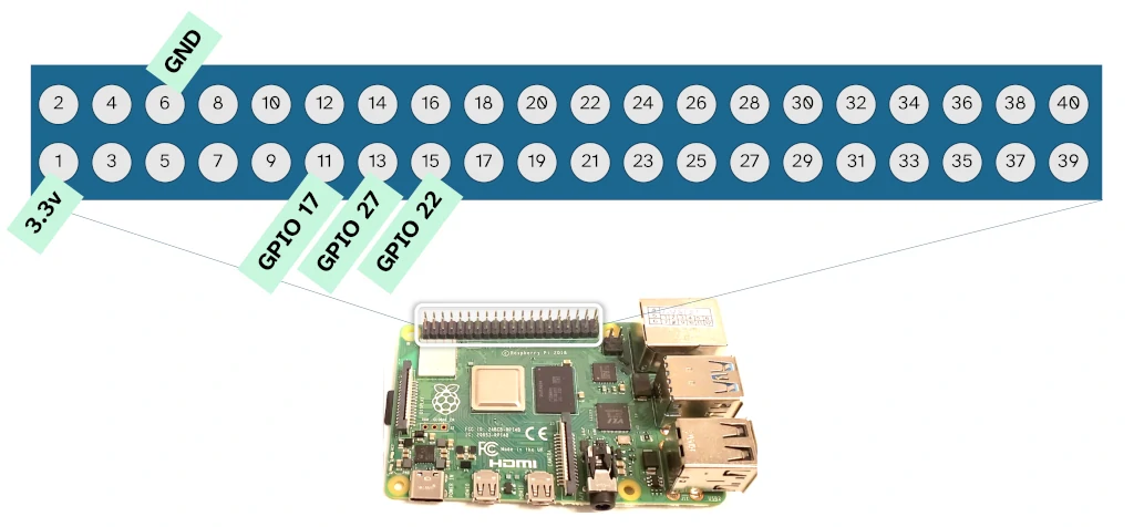
GPIO pin numbering does not match the physical numbering on the Raspberry Pi board. For more detail and alternative pins that you can use, check out the pin diagram here.
SPI and I2C are more advanced communication protocols that allow two way communication with the sensor device (you can send it commands from your code, as well as read back data).
While it should be possible to connect multiple outputs from a single sensor to the Raspberry Pi, I don’t recommend doing it. Unless the manufacturer explicitly states this is ok, it might cause problems with readings depending on in the internals of the sensor.
If you’re not sure on the sensor’s output, try the following:
- Reading the datasheet of device – even the most basic sensors typically have a datasheet describing their characteristics and how to connect them
- Examining the board – many sensors bought for Raspberry Pi projects arrive mounted on a simple integrated circuit, this is often labelled with hints on how to connect it
I’ve occasionally had trouble finding the right datasheet for my device when using Google. Often this is because the manufacturer provides a generic datasheet for a series of their devices which have mostly the same characteristics but vary slightly (e.g. pin type). Keep an eye out for functionally similar devices (and their datasheets) from the same manufacturer if you can’t find the exact one for your sensor.
Step 2: Wire the circuit
The sensor needs to be wired to the GPIO to form a circuit. Typically this includes other components, such as a resistor and/or a capacitor. When experimenting with a Raspberry Pi project, it’s often easier to plug all of these components into a breadboard to form the circuit. In the final product, components should be mounted to a circuit board.
I often wire sensors directly to the GPIO without any other components. This is a bad practice and I might one day damage my Raspberry Pi while doing it.
Good practice is to include typically a resistor and/or capacitor in the circuit to smooth the current a bit. A set of resistors performing the role of a voltage divider may also be needed to ensure your sensor outputs at the Raspberry Pi GPIO requirement of 3.3V.
Components typically required to wire a sensor to the Raspberry Pi are included below:
| Component | Purpose |
|---|---|
| Resistor | To hold the voltage for a digital signal high or low, keeping it out of an undefined state. |
| Capacitor | To filter out noise from the signal. |
| Transistor | To amplify a signal. Usually not necessary in a basic Raspberry Pi sensor circuit. |
| ADC | Analog-to-digital converter, used to convert the signal from an analog sensor to a set of digital numbers that can be used by code running on the Pi. |
If using an analog sensor with an ADC, you will also likely need to wire the sensor to the GPIO (unless it’s an ADC hat).
For the type of wire to use, you will most likely need 22 AWG jumper wire with female ends. If using a breadboard, you might need a male end for connecting the jumper wire to the breadboard. If you need more detail on the type of wire to use with Raspberry Pi, check out my guide here: chipwired.com/raspberry-pi-wires.
Step 3: Write code to read from the sensor
Python is the easiest language to use when writing code to read from a sensor connected to a Raspberry Pi. To read from a sensor using Python you need to import a GPIO library, configure the GPIO pins for reading or communication, then use the library to read the sensor.
Overall my preferred library is RPi.GPIO, though the table below lists examples of the libraries you can use to read from a sensor:
| Sensor Communication Type | Library |
|---|---|
| Digital input (single wire) | RPi.GPIO |
| Analog input | Circuitpython ADC library |
| SPI, I2C, or UART | Circuitpython SPI and I2C library |
| USB or Bluetooth | Drivers recommended by the sensor manufacturer |
An example of the code that I used to read from a digital input sensor is as follows:
import RPi.GPIO as GPIO

GPIO.setmode(GPIO.BCM)
GPIO.setup(17, GPIO.IN)

print(GPIO.input(17))
In this simple code example we do the following:
- Import the RPi.GPIO library (and call it GPIO)
- Set the mode of the GPIO to BCM (to align with our GPIO numbering)
- Set the GPIO pin 17 to be an input pin
- Read from pin 17 and print it to the command line
If using one of the other sensor types, your code will be more complicated and depend more on the type of sensor and way you communicate with it. The basics are still the same though: Import the library; setup the hardware; read from the sensor.
For more detail on the variety of ways Raspberry Pi can collect data (and it’s not limited to only sensors), check out the guide I wrote here: chipwired.com/collect-data-with-raspberry-pi
Data read from a sensor, or collected by other means, is typically used in making decisions that the Raspberry Pi will enact. The diversity of these actions are why I love Raspberry Pi: Based on sensor data it can update your calendar, light up an LED, display something on a monitor, turn the wheels of a robot, and much more!
Data read from the sensor can also be saved to the Raspberry Pi for further analysis later. The most popular ways I’ve found to save sensor data on a Raspberry Pi include:
- CSV file
- Cloud storage (uploaded using an API)
- SQL database (such as SQLite)
These data storage methods make it easy to analyse the data later, such as by using Excel or other data analysis tools. For more detail on data storage for Raspberry Pi, check out my guide here: chipwired.com/raspberry-pi-store-data